800 VDC sidecar battery · 400–600 kW per cabinet
The GPU cluster steps load in milliseconds. The bus has to hold.
NVIDIA has designated 800 V DC as the native distribution architecture for its next-generation AI racks. That removes the low-voltage AC UPS from the power chain — and it removes the place your ride-through energy used to live.
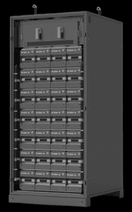
This is where it lives now. A cabinet that parallels straight onto the 800 V bus, carries its own bidirectional conversion, and picks up the load in under three milliseconds when the front end sags.
Datasheet, application note, mechanical drawings, rack-level and server-level interconnect, and current certification status.
If you are designing an 800 V hall
Moving to DC solves five problems and creates one: where does the energy sit?
- The AC UPS is gone from the design, and with it the battery cabinet that used to be a line item on somebody else's drawing.
- Your front end — rectifier stack or solid-state transformer — regulates the bus, but it has no stored energy behind it, so a supply event is a load event.
- Ride-through has to be measured in milliseconds now, because a GPU cluster does not tolerate a bus excursion the way a general-purpose load does.
- Capacity you buy for the fully built-out hall is capacity you finance for years before you use it, and UPS-attached batteries have to be bought in frame-sized steps.
- Any lithium in the white space brings NFPA 855, UL 9540A spacing consequences, and a plan reviewer who will ask which listing, by model.
- A single large converter in front of the bank is a single point of failure that takes a maintenance window to touch.
Why the architecture changed
Three conversions became two, and the battery stopped being a passenger.
The AC chain went 10 kV AC to 380 V AC, rectified to DC, inverted back to AC, then rectified again inside the server supply. Every stage is a loss and a component that can fail. The 800 V DC chain converts once at the front and once at the server.
AC UPS architecture
AC → DC → AC → DC
Three conversions before the silicon. Rectifier 2–3 %, inverter 4–5 %, server supply 3–5 %. Scaling means growing UPS frames and battery strings together.
800 V HVDC architecture
AC → DC → DC
Two conversions. Front end 2–3 %, server supply 2.8–4 %. Over five percent better end-to-end than the AC chain, with fewer failure nodes and less floor space consumed by conversion gear.
The efficiency argument gets the architecture approved. The decoupling argument is what changes your capital plan.
Because the DC bus is modular, power supply and energy storage stop being one purchase. Ride-through gets added a cabinet at a time, against real load growth, instead of being sized for the hall you intend to have in three years.
What the module actually does
Float, boost, ramp out. All three thresholds are yours to set.
- 01
Bus healthy
Buck — float charge
The front end regulates the bus above 784 V and the module steps 800 V down to charge its pack at 54.4 V, 30 A. Once full it sits in standby. It is not idle capital sitting in a room; it is a device on the bus.
- 02
Bus sags
Boost — discharge
Bus voltage crosses below 775 V and the module boosts within 3 milliseconds, holding 780 ±4 V DC with better than 97 % conversion efficiency. Twenty-four modules in parallel deliver up to 600 kW for more than five minutes at end of life.
- 03
Supply returns
Ramp out — soft transfer
Bus above 785 V for more than 200 milliseconds — a deliberate debounce, not a hair trigger — and the module walks its output down at 100 V per second. The load moves back to the front end on a slope, then the pack recharges.
Every threshold above — charge enable, discharge activation, discharge exit, debounce duration, output setpoint — is configurable, because the coordination that matters is between this cabinet and the specific front end and load you are pairing it with, not with a number we picked in a lab.
Cabinet configurations
You populate the rack to the ride-through you need, not to a frame size.
One cabinet, five populations. Every module is identical, so the step between configurations is two modules — not a different product, a different quotation cycle, and a different set of drawings.
| Modules in parallel | Max power (5 min, EOL) | Rated energy | Weight |
|---|---|---|---|
| 16 | 400 kW | 49.15 kWh | ≈1,254 kg |
| 18 | 450 kW | 55.30 kWh | ≈1,328 kg |
| 20 | 500 kW | 61.44 kWh | ≈1,402 kg |
| 22 | 550 kW | 67.58 kWh | ≈1,476 kg |
| 24 | 600 kW | 73.73 kWh | ≈1,550 kg |
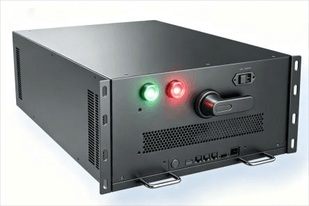
Cabinet 1,000 × 1,100 × 2,000 mm, IP54, 1,000 mm front clearance required. Module 180 × 980 × 200 mm, ≈37 kg, 25 kW. Nominal pack 51.2 V 60 Ah (10C), 3.072 kWh per module. Modbus RTU over RS-485, CAN bus, Modbus TCP/IP, and dry contacts. Operating range 0–45 °C, 15–35 °C recommended.
The numbers that survive a design review
Every figure here is on the datasheet. What matters is what each one buys you.
≤ 3 ms discharge response
Fast enough that the bus excursion never reaches the server supplies as a fault. This is the number that decides whether a supply event is an incident or a log entry.
> 5 minutes at 600 kW, at end of life
Rated on a worn cell, not a new one, so the figure still holds in year eight. Long enough to start a generator or to checkpoint and park a cluster in an orderly way.
600 kW in a single 1.0 × 1.1 m footprint
Proprietary 10C cells give roughly 60 percent more rate capability, which is what collapses the floor area. In a hall where white space is the scarce resource, density is a commercial number, not a technical one.
> 97 % discharge, > 95 % charge conversion
Losses in the storage path are small enough that they do not eat the efficiency you just won by removing a conversion stage from the architecture.
One module = 4.17 % of system power
A failure is a derate, not an outage, and a replacement is a slide-in on live equipment. Mean time to repair is measured in minutes, not in maintenance windows.
Microsecond-level current sharing
Closed-loop digital control over CAN keeps 24 parallel converters evenly loaded and suppresses circulating current between them. Even loading is why the system reaches its rated life.
The hardware
A converter, a pack, and a fire strategy — repeated 24 times.
The design decision underneath everything on this page is that there is no central converter. Each module is a complete 25 kW power conversion system with its own cells, its own bidirectional DC/DC, its own balancing, and its own suppression.
“Stacked or wound — is that a real distinction or a spec-sheet flourish?”
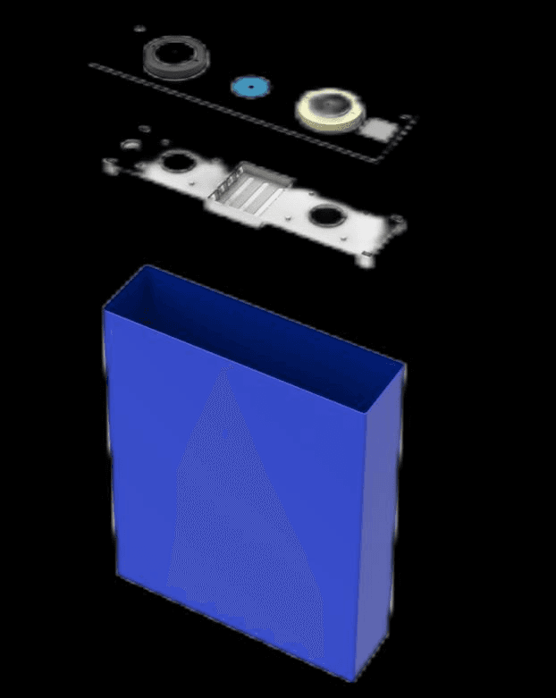
At 10C it is real. Stacking parallels multiple electrodes, which lowers internal resistance and therefore lowers the heat generated during a high-rate pulse. A wound cell has corners; corners mean uneven reaction rate across the electrode, which means hot spots, which means the active material in those regions degrades first and drags the rest of the cell with it. Stacking also uses the can volume better, which is where the density comes from.
“Who made the cell?”
We did. This cabinet is built on a cell we designed and manufacture, on a line we control. That matters for two unglamorous reasons: process-control and incoming-material documentation exist and can be handed to you during qualification, and change notification can be written into the supply agreement. An integrator who buys cells cannot offer either, because they do not own the line.
“Twenty-four converters sounds like twenty-four things that can fail.”
It is — and that is the point. Twenty-four independent failure domains each worth 4.17 percent of system power, in a hot-swappable package, is a fundamentally better risk position than one converter worth 100 percent that requires a maintenance window. Redundancy is N+X by populating spare module slots, not by buying a second cabinet.
Fire and thermal strategy
Three independent layers, and the earliest one watches for gas rather than smoke.
Lithium in the white space is the part of this conversation your authority having jurisdiction will care about most. Suppression here is not a single cabinet-level bottle bolted on at the end of the design.
Layer 1 — module
Perfluorohexanone inside every module
160 g of agent, a thermal fuse wire routed through the module interior, activation at 185 ±15 °C, discharge in under five seconds into a 0.2 m³ protected space. The event is cooled and starved of oxygen inside the module that started it.
Layer 2 — cabinet
Pulse atomization, dual-sensor triggered
Combined thermal and smoke sensing arms a larger unit protecting 5 m³. Pulse atomization fills the cabinet with an ultra-fine mist that breaks the combustion chain while cooling and displacing oxygen.
Layer 0 — detection
Off-gas detection, before there is smoke
Hydrogen resolved at 10 ppm per second and electrolyte vapour below 1 ppm per second, alarming at 4,000 ppm and 1,500 ppm respectively, with a five-second response. A venting cell announces itself in gas long before it announces itself in smoke.
Perfluorohexanone was chosen over a solid or powder agent for a specific reason: it fully vaporises after discharge, remains non-conductive, and leaves no solid contaminant on the electronics around it. A suppression event should not be indistinguishable from a cabinet replacement.
Where this is going
800 V DC is not a bet on a standard. The standard has already been set by the people buying the racks.
Who is driving it
- NVIDIA has designated 800 V HVDC as the native distribution standard for its next-generation AI racks. The rack vendor sets the power spec now, and everything upstream follows.
- Meta, Google and Microsoft are moving to 800 V in new North American AI factories from 2027, with the Open Compute Project driving the open standards underneath.
- The major power vendors are building full HVDC ecosystems — solid-state transformers and high-efficiency 800 V rectifiers at the front, intelligent DC distribution in the middle, sidecar rack-level storage at the back.
What that means for your schedule
Penetration in newly built AI data centers is expected to pass 50 percent by 2028, which puts the architecture decision inside the design window of anything being planned now. The uncomfortable part is the qualification cycle: on a typical regional AI build, vendor shortlisting starts on day one of funding and selection closes around the end of year one, with the order placed early in year two.
Qualification takes months, not weeks. The argument for starting it now is that nothing is on fire now.
Questions engineers actually ask
Answers, including the ones that come as a document rather than a sentence.
What does “sidecar” actually mean here?
It means the battery is a peer on the DC bus rather than a subsystem inside a UPS. In an AC architecture the battery lives behind the UPS, so capacity is capped by the rated power of the UPS frame and you expand both together. On an 800 V DC bus the rectification and the energy storage are decoupled — each cabinet carries its own bidirectional DC/DC and parallels onto the bus. You add ride-through by adding cabinets, on the schedule the load actually grows, without touching the front end.
How fast does it pick up the load?
Discharge response is 3 milliseconds or less. The module watches bus voltage: below 775 V it boosts and holds 780 ±4 V DC. When the bus comes back above 785 V and stays there for more than 200 milliseconds, it ramps its output down at 100 V per second so the transfer back to the front end is a slope rather than a step. Every one of those thresholds is configurable to match the rectifier or solid-state transformer you are actually pairing it with.
How long does it hold?
More than five minutes at 600 kW per cabinet, measured at end of life rather than on a new cell. This is ride-through and orderly-shutdown duty — it holds the DC bus while the generator starts, the utility recovers, or the cluster checkpoints and parks. It is not a substitute for a generator and we would not sell it as one.
What happens when one module fails?
You lose 4.17 percent of maximum system power and nothing else. Modules are hot-swappable on dedicated hot-swap terminals with a slide-in contact design, so you replace one without shutting the system down and without dropping the bus. The remaining modules in parallel carry the load. That is the reason the architecture is 24 small converters instead of one large one.
How do 24 parallel converters share current without fighting each other?
Each module has an embedded MCU; a central battery management controller closes the loop over CAN with real-time digital current-sharing control. Practically, that does three things: it keeps modules within microsecond-level sharing accuracy, it suppresses reverse circulating current between modules in discharge, and it keeps every module inside its thermal limit instead of letting one unit take the brunt. Uneven loading is what shortens the life of a parallel power system.
What is the fire strategy?
Three independent layers rather than one. Each module carries its own perfluorohexanone suppression unit — 160 g of agent, a thermal fuse wire routed through the module, activation at 185 ±15 °C, discharge in under five seconds. The cabinet carries a second, larger pulse-atomization unit triggered by combined thermal and smoke sensing. Above both, an off-gas detector watches for hydrogen and electrolyte vapour, which appear before there is anything to see or feel. Perfluorohexanone fully vaporises, is non-conductive, and leaves no solid residue on electronics.
Why does off-gas detection matter more than a smoke detector?
Because it moves your warning to the left. A cell venting electrolyte gives off hydrogen and solvent vapour well before thermal runaway propagates. The unit resolves hydrogen at 10 ppm per second and electrolyte vapour below 1 ppm per second, alarms at 4,000 ppm hydrogen or 1,500 ppm electrolyte vapour, and responds in five seconds. Smoke means you are already late.
Is the cell yours, and does the construction matter?
It is ours — a 3.2 V 60 Ah 10C LiFePO4 prismatic cell built on a stacked (laminated) electrode process, not a wound jelly roll. At 10C the difference is not marketing. Stacking puts multiple electrodes in parallel, which drops internal resistance below 0.5 mΩ and therefore drops heat generated during a high-rate pulse. Wound cells carry corners, and corners mean uneven reaction rate, hot spots, and faster local degradation. For a cell that has to deliver 600 A on demand and then sit at float, that is the whole ballgame.
What certifications does it carry?
Certification status is answered by document for the exact model and revision you intend to install, not by a general statement on a web page — your plan reviewer will ask by name. Ask us for the current package and you will get the certificates that exist and the schedule for anything in test. For the standards themselves: UL 1973 covers the battery at component and module level, UL 9540 is the system listing, UL 9540A is the fire-propagation test method whose results drive spacing and suppression, UL 1741 covers the conversion equipment, NFPA 855 governs installation, and NEC Article 706 governs the electrical work. Call (408) 309-1021 and ask for the compliance package.
What do I need from you to put this in a drawing?
The full datasheet, the application note for your architecture, mechanical drawings with clearances, and the rack-level and server-level interconnect detail. A cabinet is 1,000 × 1,100 × 2,000 mm with 1,000 mm of front clearance required, IP54, and 1,550 kg fully populated — floor loading and door height eliminate options late in a design, so take those numbers early. Ask and we will send the set.
Talk to an application engineer
Tell us the bus, the load step, and the hold time. We will tell you the module count.
You will get the datasheet, the application note for your architecture, mechanical drawings with clearances, the rack-level and server-level interconnect detail, and the current certification package — for the exact model and revision, not for the product line.
Faster route: (408) 309-1021, Monday–Friday, 8:00–5:00 Central.